The documentation set for this product strives to use bias-free language. For the purposes of this documentation set, bias-free is defined as language that does not imply discrimination based on age, disability, gender, racial identity, ethnic identity, sexual orientation, socioeconomic status, and intersectionality. Exceptions may be present in the documentation due to language that is hardcoded in the user interfaces of the product software, language used based on RFP documentation, or language that is used by a referenced third-party product. Learn more about how Cisco is using Inclusive Language.
This document describes the effect of Policy Based Routing (PBR) and local PBR when applied to Encapsulating Security Payload (ESP) and Internet Security Association and Key Management Protocol (ISAKMP) packets when you use Cisco IOS ® . Contributed by Michal Garcarz, Cisco TAC Engineer.
The information in this document is based on Cisco IOS Version 15.x.
The information in this document was created from the devices in a specific lab environment. All of the devices used in this document started with a cleared (default) configuration. If your network is live, make sure that you understand the potential impact of any command.
Prior to IPsec tunnel establishment, the router initiates an ISAKMP exchange. As those packets are generated by the router, the packets are treated as locally generated traffic and any local PBR decisions are applied. In addition, any packets generated by the router (Enhanced Interior Gateway Routing Protocol (EIGRP), Next Hop Resolution Protocol (NHRP), Border Gateway Protocol (BGP), or Internet Control Message Protocol (ICMP) pings) are also considered as locally generated traffic and have the local PBR decision applied.
Traffic that is forwarded by the router and sent across the tunnel, which is called transit traffic, is not considered locally generated traffic, and any desired routing policy must be applied on the ingress interface of the router.
The implications this has on traffic that traverses the tunnel is that the locally generated traffic follows PBR, but transit traffic does not. This article explains the consequences of this difference in behavior.
For transit traffic that needs to be ESP encapsulated, there is no need to have any routing entries because PBR determines the egress interface for the packet before and after ESP encapsulation. For locally generated traffic that needs to be ESP encapsulated, it is necessary to have routing entries, because local PBR determines the egress interface only for the packet before encapsulation and the routing determines the egress interface for the post-encapsulated packet.
This document contains a typical configuration example where one router with two ISP links is used. One link is used in order to access the Internet and the second is for VPN. In case of any link failure, traffic is rerouted with a different Internet Service Provider (ISP) link. Pitfalls are also presented.
Please notice that PBR is performed in Cisco Express Forwarding (CEF), whereas local PBR is process-switched.
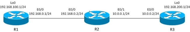
This section describes the behavior of traffic initiated from router (R)1. That traffic is ESP encapsulated by R1.
The IPsec LAN-to-LAN tunnel is built between R1 and R3.
The interesting traffic is between R1 Lo0 (192.168.100.1) and R3 Lo0 (192.168.200.1).
The R3 router has a default route to R2.
R1 has no routing entries, only directly connected networks.
R1 has local PBR for all traffic:
interface Loopback0
ip address 192.168.100.1 255.255.255.0
!
interface Ethernet0/0
ip address 192.168.0.1 255.255.255.0
crypto map CM

track 10 ip sla 10
ip sla 10
icmp-echo 192.168.0.2 source-ip 192.168.0.1

route-map LOCALPBR permit 10
set ip next-hop verify-availability 192.168.0.2 1 track 10
ip local policy route-map LOCALPBR
All locally generated traffic on R1 is sent to R2 when it is UP.
In order to verify what occurs when you bring up the tunnel, send the interesting traffic from the router itself:
R1#debug ip packet
R1#ping 192.168.200.1 source lo0
Caution: The debug ip packet command might generate a large amount of debugs and has huge impact on CPU usage. Use it with caution.
This debug also allows the access-list to be used in order to limit the amount of traffic processed by debugs. The debug ip packet command only displays traffic that is process-switched.
Here are the debugs on R1:
IP: s=192.168.100.1 (local), d=192.168.200.1 (Ethernet0/0), len 100, local
feature, Policy Routing(3), rtype 2, forus FALSE, sendself FALSE, mtu 0, fwdchk
FALSE
IP: s=192.168.100.1 (local), d=192.168.200.1 (Ethernet0/0), len 100, sending
IP: s=192.168.100.1, d=192.168.200.1, pak EF6E8F28 consumed in output feature,
packet consumed, IPSec output classification(30), rtype 2, forus FALSE, sendself
FALSE, mtu 0, fwdchk FALSE
IP: s=192.168.0.1 (local), d=10.0.0.2 (Ethernet0/0), len 192, local feature, Policy
Routing(3), rtype 2, forus FALSE, sendself FALSE, mtu 0, fwdchk FALSE
IP: s=192.168.0.1 (local), d=10.0.0.2 (Ethernet0/0), len 192, sending
IP: s=192.168.0.1 (local), d=10.0.0.2 (Ethernet0/0), len 192, output feature,
IPSec output classification(30), rtype 2, forus FALSE, sendself FALSE, mtu 0,
fwdchk FALSE
IP: s=192.168.0.1 (local), d=10.0.0.2 (Ethernet0/0), len 192, output feature,
IPSec: to crypto engine(64), rtype 2, forus FALSE, sendself FALSE, mtu 0,
fwdchk FALSE
IP: s=192.168.0.1 (local), d=10.0.0.2 (Ethernet0/0), len 192, output feature,
Post-encryption output features(65), rtype 2, forus FALSE, sendself FALSE, mtu 0,
fwdchk FALSE
IP: s=192.168.0.1 (local), d=10.0.0.2 (Ethernet0/0), len 192, post-encap feature,
(1), rtype 2, forus FALSE, sendself FALSE, mtu 0, fwdchk FALSE
IP: s=192.168.0.1 (local), d=10.0.0.2 (Ethernet0/0), len 192, post-encap feature,
FastEther Channel(3), rtype 2, forus FALSE, sendself FALSE, mtu 0, fwdchk FALSE
IP: s=192.168.0.1 (local), d=10.0.0.2 (Ethernet0/0), len 192, sending full packet
Here is what happens:
The interesting traffic (192.168.100.1 > 192.168.200.1) is matched by local PBR, and the egress interface is determined (E0/0). This action triggers the crypto code to initiate ISAKMP. That packet is also policy-routed by local PBR, which determines the egress interface (E0/0). The ISAKMP traffic is sent, and the tunnel is negotiated
What happens when you ping again?
R1#show crypto session
Crypto session current status

Interface: Ethernet0/0
Session status: UP-ACTIVE
Peer: 10.0.0.2 port 500
IKEv1 SA: local 192.168.0.1/500 remote 10.0.0.2/500 Active
IPSEC FLOW: permit ip host 192.168.100.1 host 192.168.200.1
Active SAs: 2, origin: crypto map

R1#ping 192.168.200.1 source lo0 repeat 1

IP: s=192.168.100.1 (local), d=192.168.200.1 (Ethernet0/0), len 100, local
feature, Policy Routing(3), rtype 2, forus FALSE, sendself FALSE, mtu 0,
fwdchk FALSE
IP: s=192.168.100.1 (local), d=192.168.200.1 (Ethernet0/0), len 100, sending
IP: s=192.168.100.1 (local), d=192.168.200.1 (Ethernet0/0), len 100, output
feature, IPSec output classification(30), rtype 2, forus FALSE, sendself FALSE,
mtu 0, fwdchk FALSE
IP: s=192.168.100.1, d=192.168.200.1, pak EEB40198 consumed in output feature,
packet consumed, IPSec: to crypto engine(64), rtype 2, forus FALSE, sendself
FALSE, mtu 0, fwdchk FALSE
IP: s=192.168.0.1 (local), d=10.0.0.2 (Ethernet0/0), len 172, output feature,
IPSec output classification(30), rtype 1, forus FALSE, sendself FALSE, mtu 0,
fwdchk FALSE
IP: s=192.168.0.1 (local), d=10.0.0.2 (Ethernet0/0), len 172, output feature,
IPSec: to crypto engine(64), rtype 1, forus FALSE, sendself FALSE, mtu 0,
fwdchk FALSE
IP: s=192.168.0.1 (local), d=10.0.0.2 (Ethernet0/0), len 172, output feature,
Post-encryption output features(65), rtype 1, forus FALSE, sendself FALSE,
mtu 0, fwdchk FALSE
IP: s=192.168.0.1 (local), d=10.0.0.2 (Ethernet0/0), g=10.0.0.2, len 172,
forward
IP: s=192.168.0.1 (local), d=10.0.0.2 (Ethernet0/0), len 172, post-encap
feature, (1), rtype 0, forus FALSE, sendself FALSE, mtu 0, fwdchk FALSE
IP: s=192.168.0.1 (local), d=10.0.0.2 (Ethernet0/0), len 172, post-encap
feature, FastEther Channel(3), rtype 0, forus FALSE, sendself FALSE, mtu 0,
fwdchk FALSE
IP: s=192.168.0.1 (local), d=10.0.0.2 (Ethernet0/0), len 172, encapsulation
failed.
Success rate is 0 percent (0/1)
Here is what happens:
The locally generated interesting traffic, 192.168.100.1 > 192.168.200.1, is locally policy-routed, and the egress interface is determined (E0/0). The packet is consumed by the IPsec output feature on E0/0 and encapsulated. The encapsulated packet (from 192.168.0.1 to 10.0.0.2) is checked for routing in order to determine the egress interface, but there is nothing in the routing tables of R1, which is why encapsulation fails.
In this scenario, the tunnel is UP, but the traffic is not sent because, after ESP encapsulation, Cisco IOS checks the routing tables in order to determine the egress interface.
This section describes the behavior for transit traffic that comes through the router, which is ESP encapsulated by that router.
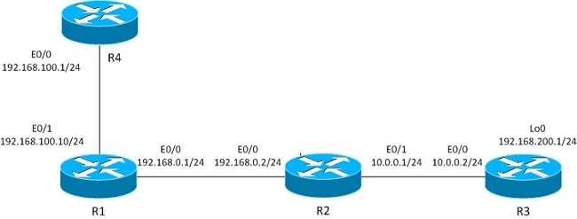
The L2L tunnel is built between R1 and R3.
The interesting traffic is between R4 (192.168.100.1) and R3 lo0 (192.168.200.1).
The R3 router has a default route to R2.
The R4 router has a default route to R1.
R1 has no routing.
The previous topology is modified in order to show the flow when the router receives packets for encryption (transit traffic instead of locally generated traffic).
Right now, the interesting traffic received from R4 is policy-routed on R1 (by PBR on E0/1), and there is also local policy routing for all traffic:
interface Ethernet0/1
ip address 192.168.100.10 255.255.255.0
ip policy route-map PBR

route-map LOCALPBR permit 10
set ip next-hop verify-availability 192.168.0.2 1 track 10
!
route-map PBR permit 10
set ip next-hop verify-availability 192.168.0.2 1 track 10

ip local policy route-map LOCALPBR
In order to verify what happens when you bring up the tunnel on R1 (after you receive the interesting traffic from R4), enter:
R1#debug ip packet
R4#ping 192.168.200.1
Here are the debugs on R1:
IP: s=192.168.100.1 (Ethernet0/1), d=192.168.200.1 (Ethernet0/0), len 100,
input feature, Policy Routing(68), rtype 2, forus FALSE, sendself FALSE, mtu 0,
fwdchk FALSE
IP: s=192.168.100.1 (Ethernet0/1), d=192.168.200.1 (Ethernet0/0), len 100,
input feature, MCI Check(73), rtype 2, forus FALSE, sendself FALSE, mtu 0,
fwdchk FALSE
IP: s=192.168.100.1, d=192.168.200.1, pak EEB4A9D8 consumed in output feature,
packet consumed, IPSec output classification(30), rtype 2, forus FALSE,
sendself FALSE, mtu 0, fwdchk FALSE
IP: s=192.168.0.1 (local), d=10.0.0.2 (Ethernet0/0), len 192, local feature,
Policy Routing(3), rtype 2, forus FALSE, sendself FALSE, mtu 0, fwdchk FALSE
IP: s=192.168.0.1 (local), d=10.0.0.2 (Ethernet0/0), len 192, sending
IP: s=192.168.0.1 (local), d=10.0.0.2 (Ethernet0/0), len 192, output feature,
IPSec output classification(30), rtype 2, forus FALSE, sendself FALSE, mtu 0,
fwdchk FALSE
IP: s=192.168.0.1 (local), d=10.0.0.2 (Ethernet0/0), len 192, output feature,
IPSec: to crypto engine(64), rtype 2, forus FALSE, sendself FALSE, mtu 0,
fwdchk FALSE
IP: s=192.168.0.1 (local), d=10.0.0.2 (Ethernet0/0), len 192, output feature,
Post-encryption output features(65), rtype 2, forus FALSE, sendself FALSE,
mtu 0, fwdchk FALSE
IP: s=192.168.0.1 (local), d=10.0.0.2 (Ethernet0/0), len 192, post-encap
feature, (1), rtype 2, forus FALSE, sendself FALSE, mtu 0, fwdchk FALSE
IP: s=192.168.0.1 (local), d=10.0.0.2 (Ethernet0/0), len 192, post-encap
feature, FastEther Channel(3), rtype 2, forus FALSE, sendself FALSE, mtu 0,
fwdchk FALSE
IP: s=192.168.0.1 (local), d=10.0.0.2 (Ethernet0/0), len 192, sending full
packet
Here is what happens:
The interesting traffic hits PBR on E0/0 and triggers crypto code to send the ISAKMP packet. That ISAKMP packet is locally policy-routed, and the egress interface is determined by local PBR. A tunnel is built.
Here is one more ping to 192.168.200.1 from R4:
R4#ping 192.168.200.1
Here are the debugs on R1:
IP: s=192.168.100.1 (Ethernet0/1), d=192.168.200.1 (Ethernet0/0), len 100,
input feature, Policy Routing(68), rtype 2, forus FALSE, sendself FALSE, mtu 0,
fwdchk FALSE
IP: s=192.168.100.1 (Ethernet0/1), d=192.168.200.1 (Ethernet0/0), len 100,
input feature, MCI Check(73), rtype 2, forus FALSE, sendself FALSE, mtu 0,
fwdchk FALSE
IP: s=192.168.100.1 (Ethernet0/1), d=192.168.200.1 (Ethernet0/0), len 100,
output feature, IPSec output classification(30), rtype 2, forus FALSE, sendself
FALSE, mtu 0, fwdchk FALSE
IP: s=192.168.100.1, d=192.168.200.1, pak EF722068 consumed in output feature,
packet consumed, IPSec: to crypto engine(64), rtype 2, forus FALSE, sendself
FALSE, mtu 0, fwdchk FALSE
IP: s=192.168.0.1 (Ethernet0/1), d=10.0.0.2 (Ethernet0/0), len 172, input
feature, Policy Routing(68), rtype 2, forus FALSE, sendself FALSE, mtu 0,
fwdchk FALSE
IP: s=192.168.0.1 (Ethernet0/1), d=10.0.0.2 (Ethernet0/0), len 172, input
feature, MCI Check(73), rtype 2, forus FALSE, sendself FALSE, mtu 0,
fwdchk FALSE
IP: s=192.168.0.1 (Ethernet0/1), d=10.0.0.2 (Ethernet0/0), len 172, output
feature, IPSec output classification(30), rtype 2, forus FALSE, sendself FALSE,
mtu 0, fwdchk FALSE
IP: s=192.168.0.1 (Ethernet0/1), d=10.0.0.2 (Ethernet0/0), len 172, output
feature, IPSec: to crypto engine(64), rtype 2, forus FALSE, sendself FALSE,
mtu 0, fwdchk FALSE
IP: s=192.168.0.1 (Ethernet0/1), d=10.0.0.2 (Ethernet0/0), len 172, output
feature, Post-encryption output features(65), rtype 2, forus FALSE, sendself
FALSE, mtu 0, fwdchk FALSE
IP: s=192.168.0.1 (Ethernet0/1), d=10.0.0.2 (Ethernet0/0), g=192.168.0.2, len
172, forward
IP: s=192.168.0.1 (Ethernet0/1), d=10.0.0.2 (Ethernet0/0), len 172, post-encap
feature, (1), rtype 0, forus FALSE, sendself FALSE, mtu 0, fwdchk FALSE
IP: s=192.168.0.1 (Ethernet0/1), d=10.0.0.2 (Ethernet0/0), len 172, post-encap
feature, FastEther Channel(3), rtype 0, forus FALSE, sendself FALSE, mtu 0,
fwdchk FALSE
IP: s=192.168.0.1 (Ethernet0/1), d=10.0.0.2 (Ethernet0/0), len 172,
sending full packet
Here is what happens:
The interesting traffic hits PBR on E0/0, and that PBR determines the egress interface (E0/0). On E0/0, the packet is consumed by IPSec and encapsulated. After the encapsulated packet is checked against the same PBR rule and the egress interface is determined, the packet is sent and received correctly.
For locally generated traffic, the egress interface for non-encapsulated traffic (ISAKMP) is determined by local PBR. For locally generated traffic, the egress interface for post-encapsulated traffic (ESP) is determined by the routing tables (local PBR is not checked). For transit traffic, the egress interface for post-encapsulated traffic (ESP) is determined by the interface PBR (twice, before and after encapsulation).
This is a practical configuration example that presents the issues you might face with PBR and local PBR with VPN. The R2 (CE) has two ISP links. The R6 router also has CE and one ISP link. The first link from R2 to R3 is used as a default route for R2. The second link to R4 is used only for VPN traffic to R6. In case of any ISP link failure, traffic is rerouted to the other link.
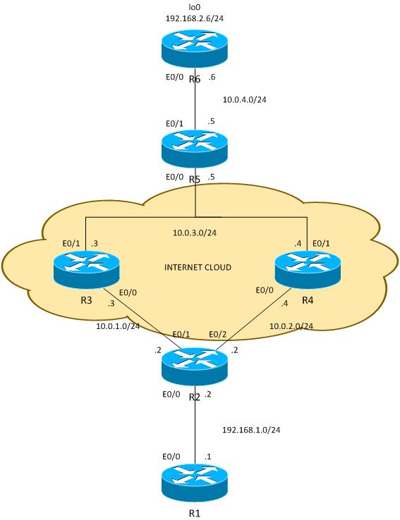
Traffic between 192.168.1.0/24 and 192.168.2.0/24 is protected. Open Shortest Path First (OSPF) is used in the Internet cloud in order to advertise the 10.0.0.0/8 addresses, which are treated as public addresses assigned by ISP to the customer. In the real world, BGP is used instead of OSPF.
The configuration on R2 and R6 is based on the crypto-map. On R2, PBR is used on E0/0 in order to direct VPN traffic to R4 if it is UP:
route-map PBR permit 10
match ip address cmap
set ip next-hop verify-availability 10.0.2.4 1 track 20

ip access-list extended cmap
permit ip 192.168.1.0 0.0.0.255 192.168.2.0 0.0.0.255

crypto map cmap 10 ipsec-isakmp
set peer 10.0.4.6
set transform-set TS
match address cmap

interface Ethernet0/0
ip address 192.168.1.2 255.255.255.0
ip nat inside
ip virtual-reassembly in
 ip policy route-map PBR
Here you see that local PBR is not needed. The interface PBR routes interesting traffic to 10.0.2.4. That triggers the crypto code to initiate ISAKMP from the correct interface (link to R4), even when the routing is to remote peer points through R3.
On R6, two peers for the VPN are used:
crypto map cmap 10 ipsec-isakmp
set peer 10.0.2.2 !primary
set peer 10.0.1.2
set transform-set TS
match address cmap
R2 uses an IP Service Level Agreement (SLA) in order to ping R3 and R4. The default route is R3. In case of R3 failure, it chooses R4:
ip sla 10
icmp-echo 10.0.1.3
ip sla schedule 10 life forever start-time now
ip sla 20
icmp-echo 10.0.2.4
ip sla schedule 20 life forever start-time now

track 10 ip sla 10
track 20 ip sla 20

ip route 0.0.0.0 0.0.0.0 10.0.1.3 track 10
ip route 0.0.0.0 0.0.0.0 10.0.2.4 100
Also R2 allows Internet access for all inside users. In order to achieve redundancy in the case where ISP to R3 is down, a route-map is necessary. It Port Address Translations (PATs) inside traffic to a different egress interface (PAT to E0/1 interface when R3 is UP and the default route points to R3, and PAT to interface E0/2 when R3 is down and R4 is used as a default route).
ip access-list extended pat
deny ip 192.168.1.0 0.0.0.255 192.168.2.0 0.0.0.255
 deny udp any any eq isakmp
 deny udp any eq isakmp any
permit ip any any

route-map RMAP2 permit 10
match ip address pat
match interface Ethernet0/2
!
route-map RMAP1 permit 10
match ip address pat
match interface Ethernet0/1

ip nat inside source route-map RMAP1 interface Ethernet0/1 overload
ip nat inside source route-map RMAP2 interface Ethernet0/2 overload

interface Ethernet0/0
ip address 192.168.1.2 255.255.255.0
 ip nat inside
ip virtual-reassembly in
ip policy route-map PBR

interface Ethernet0/1
ip address 10.0.1.2 255.255.255.0
 ip nat outside
ip virtual-reassembly in
 crypto map cmap

interface Ethernet0/2
ip address 10.0.2.2 255.255.255.0
 ip nat outside
ip virtual-reassembly in
 crypto map cmap
VPN traffic needs to be excluded from translation as does ISAKMP. If ISAKMP traffic is not excluded from translation, it is PATed to the outside interface that goes towards R3:
R2#show ip nat translation
Pro Inside global Inside local Outside local Outside global
udp 10.0.1.2:500 10.0.2.2:500 10.0.4.6:500 10.0.4.6:500

*Jun 8 09:09:37.779: IP: s=10.0.2.2 (local), d=10.0.4.6, len 196, local
feature, NAT(2), rtype 0, forus FALSE, sendself FALSE, mtu 0, fwdchk FALSE
*Jun 8 09:09:37.779: IP: s=10.0.2.2 (local), d=10.0.4.6 (Ethernet0/1),
len 196, sending
*Jun 8 09:09:37.779: IP: s=10.0.1.2 (local), d=10.0.4.6 (Ethernet0/1), len 196,
output feature, Post-routing NAT Outside(24), rtype 1, forus FALSE, sendself
FALSE, mtu 0, fwdchk FALSE
*Jun 8 09:09:37.779: IP: s=10.0.1.2 (local), d=10.0.4.6 (Ethernet0/1), len 196,
output feature, Common Flow Table(27), rtype 1, forus FALSE, sendself FALSE,
mtu 0, fwdchk FALSE
*Jun 8 09:09:37.779: IP: s=10.0.1.2 (local), d=10.0.4.6 (Ethernet0/1), len 196,
output feature, Stateful Inspection(28), rtype 1, forus FALSE, sendself FALSE,
mtu 0, fwdchk FALSE
*Jun 8 09:09:37.779: IP: s=10.0.1.2 (local), d=10.0.4.6 (Ethernet0/1), len 196,
output feature, IPSec output classification(34), rtype 1, forus FALSE, sendself
FALSE, mtu 0, fwdchk FALSE
*Jun 8 09:09:37.779: IP: s=10.0.1.2 (local), d=10.0.4.6 (Ethernet0/1), len 196,
output feature, NAT ALG proxy(59), rtype 1, forus FALSE, sendself FALSE, mtu 0,
fwdchk FALSE
*Jun 8 09:09:37.779: IP: s=10.0.1.2 (local), d=10.0.4.6 (Ethernet0/1), len 196,
output feature, IPSec: to crypto engine(75), rtype 1, forus FALSE, sendself FALSE,
mtu 0, fwdchk FALSE
*Jun 8 09:09:37.779: IP: s=10.0.1.2 (local), d=10.0.4.6 (Ethernet0/1), len 196,
output feature, Post-encryption output features(76), rtype 1, forus FALSE, sendself
FALSE, mtu 0, fwdchk FALSE
*Jun 8 09:09:37.779: IP: s=10.0.1.2 (local), d=10.0.4.6 (Ethernet0/1), len 196,
pre-encap feature, IPSec Output Encap(1), rtype 1, forus FALSE, sendself FALSE,
mtu 0, fwdchk FALSE
*Jun 8 09:09:37.779: IP: s=10.0.1.2 (local), d=10.0.4.6 (Ethernet0/1), len 196,
 pre-encap feature, Crypto Engine(3), rtype 1, forus FALSE, sendself FALSE, mtu 0,
fwdchk FALSE
*Jun 8 09:09:37.779: IP: s=10.0.1.2 (local), d=10.0.4.6 (Ethernet0/1), len 196,
sending full packet
With this configuration, there is a full redundancy. The VPN uses the R4 link, and the rest of the traffic is routed with R3. In case of R4 failure, VPN traffic is established with the R3 link (the route-map for PBR does not match and default routing is used).
Before the ISP to R4 is down, R6 sees traffic from peer 10.0.2.2:
R6#show crypto session
Crypto session current status

Interface: Ethernet0/0
Session status: UP-ACTIVE
Peer: 10.0.2.2 port 500
IKEv1 SA: local 10.0.4.6/500 remote 10.0.2.2/500 Active
IPSEC FLOW: permit ip 192.168.2.0/255.255.255.0 192.168.1.0/255.255.255.0
Active SAs: 2, origin: crypto map
After R2 uses ISP to R3 for VPN traffic, R6 sees traffic from peer 10.0.1.2:
R6#show crypto session
Crypto session current status

Interface: Ethernet0/0
Session status: UP-ACTIVE
Peer: 10.0.1.2 port 500
IKEv1 SA: local 10.0.4.6/500 remote 10.0.1.2/500 Active
IPSEC FLOW: permit ip 192.168.2.0/255.255.255.0 192.168.1.0/255.255.255.0
Active SAs: 2, origin: crypto map
For the opposite scenario, when the link to R3 goes down, everything still works fine. VPN traffic still uses the link to R4. Network Address Translation (NAT) is performed for 192.168.1.0/24 to PAT in order to appropriate the outside address. Before R3 goes down, there is a translation to 10.0.1.2:
R2#show ip nat translations
Pro Inside global Inside local Outside local Outside global
icmp 10.0.1.2:1 192.168.1.1:1 10.0.4.6:1 10.0.4.6:1
After R3 goes down, there is still the old translation along with the new translation (to 10.0.2.2) that uses the link towards R4:
R2#show ip nat translations
Pro Inside global Inside local Outside local Outside global
icmp 10.0.2.2:0 192.168.1.1:0 10.0.4.6:0 10.0.4.6:0
icmp 10.0.1.2:1 192.168.1.1:1 10.0.4.6:1 10.0.4.6:1
If everything works fine, where are the pitfalls? They are in the details.
Here is a scenario that needs to initiate VPN traffic from the R2 itself. This scenario requires you to configure local PBR on R2 in order to force R2 to send ISAKMP traffic via R4 and to cause the tunnel to go UP. But the egress interface is determined with the use of routing tables, with the default pointing to R3, and that packet is sent to R3, instead of R4, which is used for transit for VPN. In order to verify that, enter:
ip access-list extended isakmp
permit udp any any eq isakmp
permit udp any eq isakmp any
 permit icmp any any

route-map LOCAL-PBR permit 10
match ip address isakmp
set ip next-hop verify-availability 10.0.2.4 1 track 20

ip local policy route-map LOCAL-PBR
In this example, Internet Control Message Protocol (ICMP) that is generated locally is forced via R4. Without that, traffic generated locally from 192.168.1.2 to 192.168.2.5 is processed with the use of routing tables and a tunnel is established with R3.
What happens after you apply this configuration? The ICMP packet from 192.168.1.2 to 192.168.2.5 is put towards R4, and a tunnel is initiated with the link to R4. The tunnel is set up:
R2#ping 192.168.2.6 source e0/0 repeat 10
Type escape sequence to abort.
Sending 10, 100-byte ICMP Echos to 192.168.2.6, timeout is 2 seconds:
Packet sent with a source address of 192.168.1.2
.
Success rate is 90 percent (9/10), round-trip min/avg/max = 4/4/5 ms

R2#show crypto session detail
Crypto session current status

Code: C - IKE Configuration mode, D - Dead Peer Detection
K - Keepalives, N - NAT-traversal, T - cTCP encapsulation
X - IKE Extended Authentication, F - IKE Fragmentation

Interface: Ethernet0/1
Session status: DOWN
Peer: 10.0.4.6 port 500 fvrf: (none) ivrf: (none)
Desc: (none)
Phase1_id: (none)
IPSEC FLOW: permit ip 192.168.1.0/255.255.255.0 192.168.2.0/255.255.255.0
Active SAs: 0, origin: crypto map
Inbound: #pkts dec"ed 0 drop 0 life (KB/Sec) 0/0
Outbound: #pkts enc"ed 0 drop 0 life (KB/Sec) 0/0

Interface: Ethernet0/2
Uptime: 00:00:06
Session status: UP-ACTIVE
Peer: 10.0.4.6 port 500 fvrf: (none) ivrf: (none)
Phase1_id: 10.0.4.6
Desc: (none)
IKEv1 SA: local 10.0.2.2/500 remote 10.0.4.6/500 Active
Capabilities:(none) connid:1009 lifetime:23:59:53
IKEv1 SA: local 10.0.2.2/500 remote 10.0.4.6/500 Inactive
Capabilities:(none) connid:1008 lifetime:0
IPSEC FLOW: permit ip 192.168.1.0/255.255.255.0 192.168.2.0/255.255.255.0
Active SAs: 2, origin: crypto map
Inbound: #pkts dec"ed 9 drop 0 life (KB/Sec) 4298956/3593
Outbound: #pkts enc"ed 9 drop 0 life (KB/Sec) 4298956/3593
Everything seems to work correctly. The traffic is sent with the correct link E0/2 towards R4. Even R6 shows that traffic is received from 10.2.2.2, which is R4's link IP address:
R6#show crypto session detail
Crypto session current status

Code: C - IKE Configuration mode, D - Dead Peer Detection
K - Keepalives, N - NAT-traversal, T - cTCP encapsulation
X - IKE Extended Authentication, F - IKE Fragmentation

Interface: Ethernet0/0
Uptime: 14:50:38
Session status: UP-ACTIVE
Peer: 10.0.2.2 port 500 fvrf: (none) ivrf: (none)
Phase1_id: 10.0.2.2
Desc: (none)
IKEv1 SA: local 10.0.4.6/500 remote 10.0.2.2/500 Active
Capabilities:(none) connid:1009 lifetime:23:57:13
IPSEC FLOW: permit ip 192.168.2.0/255.255.255.0 192.168.1.0/255.255.255.0
Active SAs: 2, origin: crypto map
Inbound: #pkts dec"ed 1034 drop 0 life (KB/Sec) 4360587/3433
Outbound: #pkts enc"ed 1029 drop 0 life (KB/Sec) 4360587/3433
But actually, there is asymmetric routing for ESP packets here. ESP packets are sent with 10.0.2.2 as a source, but are put on the link towards R3. An encrypted response is returned through R4. This can be verified by checking counters on R3 and R4:
R3 counters of E0/0 before sending 100 packets:
R3#show int e0/0 | i pack
5 minute input rate 0 bits/sec, 0 packets/sec
5 minute output rate 0 bits/sec, 0 packets/sec
 739 packets input, 145041 bytes, 0 no buffer
0 input packets with dribble condition detected
 1918 packets output, 243709 bytes, 0 underruns
And the same counters, after sending 100 packets:
R3#show int e0/0 | i pack
5 minute input rate 0 bits/sec, 0 packets/sec
5 minute output rate 0 bits/sec, 0 packets/sec
839 packets input, 163241 bytes, 0 no buffer
0 input packets with dribble condition detected
1920 packets output, 243859 bytes, 0 underruns
The number of incoming packets increased by 100 (on the link towards R2), but the outgoing packets increased only by 2. So R3 only sees the encrypted ICMP echo.
The response is seen on R4, before sending 100 packets:
R4#show int e0/0 | i packet
5 minute input rate 0 bits/sec, 0 packets/sec
5 minute output rate 1000 bits/sec, 1 packets/sec
793 packets input, 150793 bytes, 0 no buffer
0 input packets with dribble condition detected
1751 packets output, 209111 bytes, 0 underruns
After sending 100 packets:
R4#show int e0/0 | i packet
5 minute input rate 0 bits/sec, 0 packets/sec
5 minute output rate 0 bits/sec, 0 packets/sec
 793 packets input, 150793 bytes, 0 no buffer
0 input packets with dribble condition detected
1853 packets output, 227461 bytes, 0 underruns
The number of packets sent towards R2 increased by 102 (encrypted ICMP reply), while the received packets increased by 0. So R4 only sees the encrypted ICMP reply. Of course, a packet capture confirms this.
Why does this happen? The answer is in the first part of the article.
Here is the flow of those ICMP packets:
This is why it is important to be extra cautious with locally generated traffic.
In many networks, Unicast Reverse Path Forwarding (uRPF) is used and traffic sourced from 10.0.2.2 could be dropped on E0/0 of R3. In that case, the ping does not work.
Is there any solution for this problem? It is possible to force the router to treat locally generated traffic as transit traffic. For that, local PBR needs to direct traffic to a bogus loopback interface from which it is routed like transit traffic.
This is not advised.
Note: It is important to be extra careful when you use NAT along with PBR (refer to the previous section about ISKMP traffic in PAT access-list).
There is also another solution that is a compromise. With the same topology as the previous example, it is possible to satisfy all the requirements without the use of PBR or local PBR. For this scenarrio, only routing is used. Only one more routing entry is added on R2, and all PBR/local PBR configurations are removed:
ip route 192.168.2.0 255.255.255.0 10.0.2.4 track 20
In total, R2 has this routing configuration:
ip route 0.0.0.0 0.0.0.0 10.0.1.3 track 10
ip route 0.0.0.0 0.0.0.0 10.0.2.4 100
ip route 192.168.2.0 255.255.255.0 10.0.2.4 track 20
The first routing entry is a default routing towards R3, when the link to R3 is UP. The second routing entry is a backup default route towards R4, when the link to R3 is down. The third entry decides which way traffic to the remote VPN network is sent, depending on the R4 link state (if R4 link is UP, traffic to the remote VPN network is sent via R4). With this configuration, there is no need for policy routing.
What is the drawback? There is no granular control using PBR any more. It is not possible to determine the source address. In this case, all traffic to 192.168.2.0/24 is sent towards R4 when it is UP, regardless of the source. In the previous example, that was controlled by PBR and the specific source: 192.168.1.0/24 is selected.
For which scenario is this solution too simple? For multiple LAN networks (behind R2). When some of those networks need to reach 192.168.2.0/24 in a secure way (encrypted) and other insecure ways (unencrypted), the traffic from insecure networks is still put on the E0/2 interface of R2 and does not hit the crypto-map. So it is sent unencrypted via a link to R4 (and the primary requirement was to use R4 only for encrypted traffic).
This kind of scenario and its requirements are rare, which is why this solution is used fairly often.
Using PBR and local PBR features along with VPNs and NAT might be complex and requires an in-depth understanding of the packet flow.
For scenarios such as those presented here, it is advised to use two separate routers - each router with one ISP link. In case of an ISP failure, traffic can be rerouted easily. There is no need for PBR, and the overall design is much simpler.
There is also a compromise solution that does not require the use of PBR, but uses static floating routing instead.
There is currently no verification procedure available for this configuration.
There is currently no specific troubleshooting information available for this configuration.